Tankfloor Inspection
Kontrolltechnik GmbH uses two types of SLOFEC® FloorScanner. The main differences are the weight, the dimensions and the testable wall thickness, respectively the application to a maximal coating thickness. The SLOFEC® FloorScanners allow to inspect tankfloors with wall thickness up to 25 mm and coatings up to 10 mm in a more effective way than other methods. The SLOFEC® FloorScanners are designed to cover the maximum of inspectable areas - including areas unreachable for other Systems.
 SLOFEC® FLOORSCANNER FS300PM.V2
testable plate thickness range :
up to 14 mm – without coating
up to 8 mm – with 4 mm coating thickness
minimal space under obstacles : 130 mm
SLOFEC® FLOORSCANNER FS400EM.V2
testable plate thickness range :
up to 25 mm – without coating
up to 12 mm – with 10 mm coating thickness
minimal space under obstacles : 300 mm
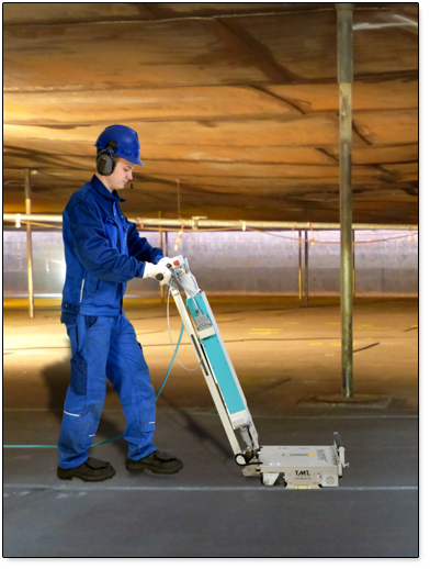
Scanning Procedure with the SLOFEC® System
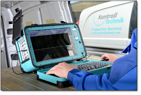
The SLOFEC® Scanner System consists of the SLOFEC® Scanner and the eddy current computer for data acquisition and data analysis.
The SLOFEC® Scanner will be operated by an assistant, who is in permanent contact with the SLOFEC® operator. The SLOFEC® operator and the scanner assistant agree the track position and the direction of scan movement. During inspection, the SLOFEC® operator records the data and analyses the signals online.
The sensor arrangement of FS300PM.V2 und FS400EM.V2 floorscanner allows the testing close to welds and to the tankwall. The untested space to the tankwall is approx. 20 mm and at both sides of longitudinal welds approx. 10 mm.
System Calibration
The depth of corrosion pits will be analysed in comparison to artificial made reference defects. In order to achieve an optimal instrument setting, a calibration plate of the same material and thickness as the plates in the tankfloor to test will be used.
During the testing indications from corrosion will be periodically re-inspected by ultrasonic test and the results compared with the result of the SLOFEC® testing. In case of deviations the SLOFEC® system can be re-adjusted in order to achieve an optimal defect depth analysis.
Advantages of the SLOFEC®-Method
- sensitive and save defect detection
- separation between signals from topside and underside defects
- separation between signals from defects and noise
- small untested zones close to the tankwall and to plate welds
- testing under installations and heating pipes down to 130 mm space
- testing of plates up to 25 mm thickness (the testable plates thickness depends on the scanner type)
- high testing speed
- no coupling fluid is necessary
- testing through non-conductive coatings up to 10 mm thickness
- comprehensive result documentation in 2D-colour scan inclusive single plate report, feature list and repair plate input
Result Documentation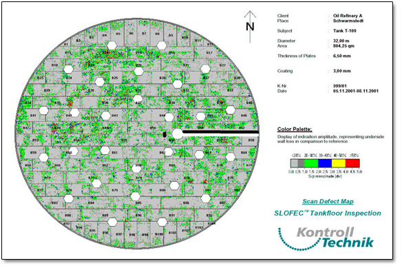
The result documentation consists of a coloured tankfloor map, single plate reports and if required feature list , repair plate map and repair plate list. In the tankfloor map and single plate reports wall thickness reductions will be shown in a 2D-scan image, where the defect depth corresponds to a defined colour.
Documentation
• Inspection overview
shows the inspected area
• Scan defect map
shows colored mapping of defects
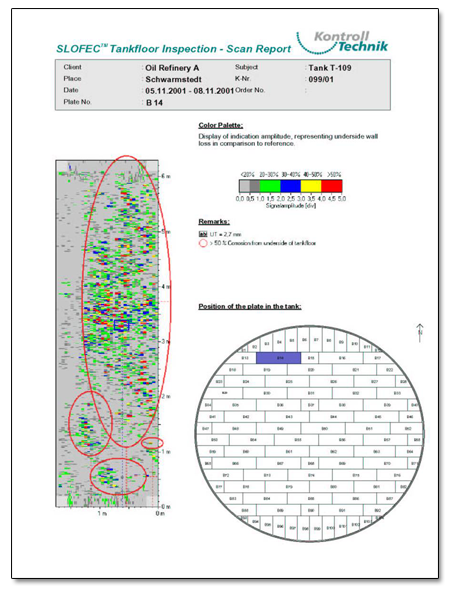
• Scan report
shows detailed colored mapping of defects in defined areas
• General settungs report
parameter of equipment, calibration and subject data